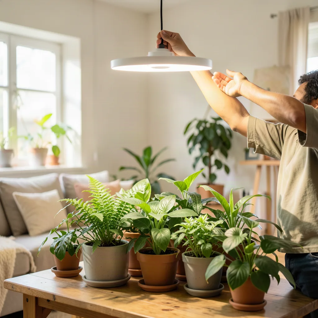
Winter brings shorter days and weaker sunlight, leaving many houseplants struggling to photosynthesize. While commercial grow lights are effective, they can be expensive and often over‑engineered for a modest indoor garden. Building your own grow lights lets you tailor spectrum, intensity, and coverage to the exact needs of each plant, and it can be done with inexpensive components you may already have. This guide walks you through the science, the parts, and the step‑by‑step builds that will keep your foliage thriving until spring.
Key takeaways
- Use a 1:1 or 3:1 blue-to-red LED ratio to balance leafy growth and flowering.
- Build constant-current drivers using LM317 regulators to ensure LED longevity.
- Monitor canopy light intensity with a quantum sensor to hit the 100-200 µmol m⁻² s⁻¹ range.
- Automate your light cycle to 12-14 hours daily using smart plugs or local controllers.
- Prioritize safety by using properly rated power supplies, thermal management, and grounding.
Understanding Light Requirements for Indoor Plants
Plants use light primarily in the blue (400‑500 nm) and red (600‑700 nm) regions. Blue light encourages compact, leafy growth, while red light drives flowering and fruiting. Most houseplants need a balanced mix, often expressed as a 1:1 or 3:1 blue‑to‑red ratio. Intensity matters too: a typical tropical houseplant wants 100‑200 µmol m⁻² s⁻¹ (PPFD) at the canopy. Measuring this with a cheap quantum sensor or a smartphone app helps you verify that your DIY fixture delivers enough energy.
Choosing the Right LED Chips
High‑efficiency white LEDs (4000‑5000 K) already contain a broad spectrum, but adding dedicated blue and red chips gives you precise control. Look for chips rated at 3 W or 5 W with a forward voltage of 3.2‑3.6 V. Reputable suppliers list the photosynthetic photon flux (PPF) per chip; aim for a total PPF of at least 30 µmol s⁻¹ per square foot of canopy. Buying in bulk (e.g., 50‑piece packs) reduces cost to under $0.30 per chip.
Designing a Simple Constant‑Current Driver
LEDs require constant current, not constant voltage. A basic driver can be built from a LM317 adjustable regulator, a sense resistor, and a heatsink. For a 3 W chip at 3.3 V, set the current to 900 mA (0.9 A). The sense resistor value = 1.25 V / 0.9 A ≈ 1.39 Ω (use a 1.5 Ω 2 W resistor). Mount the LM317 on a small aluminum heatsink and add a 10 µF electrolytic capacitor on the input and a 1 µF ceramic on the output for stability. This driver costs under $2 and can power 4‑6 chips in series.
Building a Modular Light Panel
Start with a 12 × 12 inch aluminum extrusion frame (often sold as LED heat‑sink profiles). Drill a grid of 1‑inch spaced holes for the LED chips. Press each chip into a thermal pad, then secure with a tiny screw or thermal epoxy. Wire the chips in series strings of 4‑6, each string fed by its own driver. Connect all drivers to a single 12 V DC power supply (e.g., a 60 W laptop brick). Add a PWM dimmer module on the 12 V line to adjust intensity without changing current. The result is a flat panel that can be hung or placed on a shelf.
Creating a Clip‑On Light for Small Pots
For individual pots, a compact clip‑on fixture works well. Use a 3‑inch aluminum heat‑sink bar, mount 2‑3 LED chips, and power them with a 5 V USB‑C power delivery board that negotiates 9 V at 2 A. A small buck converter steps the voltage down to the LED forward voltage while maintaining constant current via a tiny LM3410 driver IC. Attach a spring‑loaded clip to the heat‑sink so the light can grip the pot rim. This unit draws <5 W and can be moved between plants as needed.
Automating Light Cycles with a Timer or Smart Plug
Consistent photoperiods are crucial. A mechanical 24‑hour timer costs $5 and works reliably. For more flexibility, plug the power supply into a Wi‑Fi smart plug (e.g., TP‑Link Kasa) and schedule sunrise‑sunset times via an app. You can also integrate a light sensor to turn the fixture off when ambient daylight exceeds a threshold, saving electricity. Keep the schedule at 12‑14 hours for most foliage plants; extend to 16 hours for flowering species.
Managing Heat and Airflow
Even efficient LEDs generate heat that can raise leaf temperature and reduce humidity. Mount each panel on a stand that leaves at least 2 inches of clearance above the canopy. Add a low‑noise 120 mm computer fan (5 V, 0.2 A) powered from the same 12 V rail, directed across the heat‑sink fins. A simple thermostat (bimetallic switch) can turn the fan on only when the heat‑sink exceeds 45 °C, extending component life and keeping the microclimate stable.
Testing, Tuning, and Safety Checks
After assembly, measure PPFD at canopy height with a quantum meter. Adjust the PWM dimmer until you hit the target range for each plant group. Verify that all connections are soldered or secured with heat‑shrink tubing; loose wires can cause flicker or fire risk. Label each driver with its current setting. Run the system for 48 hours, monitoring temperature of the heat‑sinks and the power supply. If any component exceeds 70 °C, add more heatsink area or reduce current.
Selecting and Wiring a Reliable Power Supply
A stable DC source is the backbone of any DIY grow light. Start by calculating the total wattage of all LED strings plus a 20 percent margin for driver losses. For a 60 watt panel array a 12 V 8 A (96 W) switching supply gives comfortable headroom and runs cool. Choose a unit with active PFC and a certified safety mark (UL, CE) to avoid nuisance tripping and fire risk. Mount the supply in a ventilated enclosure separate from the light panel; this isolates heat and makes future maintenance easier.
Wire gauge matters more than many builders realize. At 12 V a 5 A draw drops roughly 0.1 V per foot of 18 AWG copper, so keep runs under three feet or step up to 16 AWG for longer leads. Use stranded silicone‑insulated wire rated for 105 °C; it flexes without cracking and tolerates the warm environment near the heatsink. Terminate each driver input with a polarized DC barrel jack (5.5 mm × 2.1 mm) and secure the connection with a crimp ferrule and heat‑shrink. Add a 2 A fast‑blow fuse on the positive rail of each driver string; a single fault will not cascade into a total system shutdown.
Grounding the metal frame eliminates shock hazard and reduces electromagnetic interference that can disturb nearby sensors. Run a green‑yellow grounding conductor from the frame to the supply’s earth terminal, then bond the supply chassis to the building ground through the AC plug. If you use a laptop‑style brick without an earth pin, attach a separate ground wire to a nearby grounded outlet using a UL‑listed grounding adapter. Finally, label every cable with heat‑resistant tags (e.g., “Panel‑A‑Driver‑1”) so troubleshooting stays fast when you expand the system.
Tailoring Spectra for Specific Plant Types
While a balanced 1:1 blue‑to‑red mix works for most foliage, certain crops thrive with a tweaked recipe. Seedlings and microgreens benefit from a higher blue fraction (≈ 3:1) to suppress elongation and promote sturdy cotyledons. Add a few 450 nm chips at 0.5 W each to a 12 × 12 inch panel and you’ll see noticeably compact growth within a week. Conversely, flowering herbs such as basil or pepper appreciate a red‑heavy blend (≈ 1:3) plus a modest far‑red component (730 nm) to accelerate phytochrome‑mediated bud set. A single 730 nm chip per 4 red chips is enough; excess far‑red can cause unwanted stem stretching.
Succulents and cacti prefer a broad white spectrum (4000‑5000 K) with a modest blue boost, because their native habitats deliver intense full‑sun light. Use high‑CRI (≥ 90) 5000 K COB modules at 10 W each, spaced 6 inches apart, and supplement with two 450 nm chips per COB. This mimics the high‑irradiance, high‑color‑rendering environment they expect without the cost of a full‑spectrum quantum board. For leafy greens that will be harvested repeatedly (lettuce, kale), a 3:1 blue‑red ratio combined with a 10 percent green (525 nm) fraction improves photosynthetic efficiency and visual quality; green photons penetrate deeper into the canopy, boosting lower‑leaf assimilation.
When mixing chip types, keep the forward voltage of each string within 0.2 V of the others so a single constant‑current driver can serve the whole series. If voltages diverge, split the string into parallel branches each with its own driver. Document the exact chip part numbers, bin codes, and measured PPF in a spreadsheet; this makes future replication or troubleshooting straightforward.
Optics, Reflectors, and Light Uniformity
Raw LED emission is Lambertian, spreading 120 degrees and creating hot spots directly under each chip. Adding a 30 degree secondary lens (acrylic or polycarbonate) over each chip narrows the beam, raises peak PPFD, and lets you space chips farther apart, reducing component count. For a 12 × 12 inch panel with 36 chips, a 30 degree lens yields a usable canopy footprint of roughly 18 × 18 inches at 12‑inch hanging height, delivering > 200 µmol m⁻² s⁻¹ across 80 percent of the area.
If you prefer a wider, more even wash, line the interior of the aluminum extrusion with a 95 percent reflective Mylar sheet (aluminum‑coated PET). Cut the sheet to the frame’s inner dimensions, fold the edges over the lip, and secure with double‑sided thermal tape. The reflector redirects side‑emitted photons back toward the canopy, boosting uniformity by 15‑20 percent without extra optics. For edge‑lit designs, a light‑guide plate (acrylic with laser‑etched micro‑structures) can spread light from a single high‑power COB across a 24 × 24 inch surface, ideal for seed‑tray racks.
Measure the resulting PAR map with a quantum sensor on a 2‑inch grid. Plot the data in a spreadsheet and calculate the coefficient of variation (CV). Aim for CV < 15 percent for most crops; higher CV indicates shadows that will cause uneven growth. Adjust lens‑to‑chip distance or add a diffuser film (0.5 mm frosted PET) to smooth outliers. Remember that diffuser films cut total output by ~10 percent, so compensate by raising driver current 5‑10 percent if thermal budget allows.
Mounting Strategies for Space‑Efficient Layouts
Ceiling‑mounted tracks give the most flexibility for rotating crops. Install a 1‑inch aluminum C‑channel along the joists, then slide T‑slot nuts into the channel to accept M5 bolts that hold each panel’s corner brackets. This lets you reposition lights in minutes when you switch from seedlings to mature plants. For shelf‑based gardens, use adjustable L‑brackets with a 0‑90 degree pivot; the bracket’s slotted hole accommodates a 6 mm carriage bolt so you can tilt the panel to follow the canopy’s angle as plants stretch.
Vertical farms benefit from a modular rack system built from 20 mm square tubing. Weld or bolt cross‑members every 12 inches, then attach panels with quick‑release clamps (spring‑loaded cam levers). The clamps distribute load evenly across the frame and allow tool‑free panel swaps for cleaning or spectrum changes. Keep the center of gravity low: place the heaviest power supplies on the bottom shelf and route DC cables through cable‑management trays that snap onto the tubing. This prevents cable fatigue and keeps the growing area tidy.
When hanging from a drop ceiling, use rated aircraft‑cable (1/8 inch, 7 × 19 strand) with a 150 lb working load limit. Attach a turnbuckle to each corner of the panel for fine height adjustment; a 1‑inch turn of the turnbuckle changes height by ~2 mm, letting you dial in the exact PPFD target without moving the whole fixture. Add a safety chain as a secondary restraint in case a cable fails. All mounting hardware should be stainless steel or zinc‑plated to resist corrosion in the humid microclimate near the plants.
Integrating with Home Automation for Dynamic Schedules
Smart plugs are a good start, but a local automation hub unlocks far richer control. Flash an ESP32 with ESPHome and connect it to the 12 V rail through a 5 V buck converter. Expose two PWM outputs: one drives the panel’s dimmer, the other drives a supplemental far‑red channel. In Home Assistant, create a “Grow Light” entity that accepts a YAML‑defined light recipe — sunrise ramp (0‑100 % over 30 minutes), midday hold, sunset fade, and a night‑time far‑red pulse (10 % for 15 minutes) to promote flowering. The ESP32 can also read a BH1750 ambient sensor and automatically dim the fixture when natural light exceeds a threshold, saving energy on bright winter days.
For multi‑zone setups, assign each panel a unique MQTT topic (e.g., “grow/zone1/set”). A Node‑RED flow can then coordinate group scenes: “Seedling Mode” sets all zones to 3:1 blue‑red at 150 µmol m⁻² s⁻¹ for 16 hours, while “Bloom Mode” shifts zones 2‑4 to 1:3 red‑blue with far‑red pulses. Because the logic lives on the LAN, there’s no cloud latency and the system continues operating even if the internet drops. Store the last known state in the ESP32’s NVS so a power cycle restores the schedule without manual intervention.
Safety interlocks are easy to add: wire a magnetic reed switch on the grow‑tent door to the ESP32’s GPIO. When the door opens, the firmware instantly cuts PWM to zero, preventing accidental eye exposure and reducing heat buildup. Log every state change to an InfluxDB instance; over weeks you’ll see correlations between light integral (DLI) and growth rates, letting you fine‑tune recipes with data rather than guesswork.
Scaling Up: Multi‑Panel Systems and Centralized Control
When you move beyond a single panel, a shared DC bus simplifies wiring and reduces component count. Run a 12 V 30 A bus bar (copper, 10 mm²) along the rack’s backbone, fed by a single 360 W mean‑well supply with remote sense. Each panel taps the bus through a 5 A polyfuse and a local buck‑constant‑current module (e.g., LM3410 based). This architecture lets you add or remove panels without re‑calculating the main supply, and the polyfuse isolates a shorted panel from the rest of the system.
Centralized dimming can be achieved with a single 0‑10 V control line run parallel to the power bus. A 0‑10 V to PWM converter (tiny op‑amp circuit) at each panel translates the analog signal to the driver’s PWM input. The automation hub drives the 0‑10 V line via a DAC module, giving you 10‑bit resolution across all zones simultaneously. If you need per‑zone intensity, insert a digital potentiometer (MCP41010) on each panel’s PWM line and address it over I²C from the ESP32; the bus only needs two extra wires (SDA, SCL) alongside the power conductors.
Monitoring becomes critical at scale. Place a DS18B20 temperature sensor on each heatsink and a INA219 current sensor on each driver’s input. Feed all readings into the same MQTT broker; a Grafana dashboard can then display real‑time PPFD estimates (derived from calibrated current‑to‑PPF curves), heatsink temperature trends, and total power draw. Set alerts for any driver exceeding 85 °C or drawing > 110 % of its rated current — early warning prevents catastrophic failure and protects the crop.
Waterproofing, Humidity Resistance, and Long‑Term Reliability
Indoor gardens often sit in humid microclimates (70‑90 % RH) where condensation can corrode solder joints and degrade LED phosphors. Conformal coat every populated PCB with a 25 µm layer of acrylic spray (e.g., MG Chemicals 422B). Mask connectors and test points with Kapton tape before spraying; after curing, remove the tape and apply a dab of dielectric grease to each barrel jack. This treatment survives occasional misting and prevents dendritic growth on exposed copper.
For panels that will be placed inside a sealed grow‑tent, upgrade the enclosure to IP65. Use a gasketed aluminum extrusion (silicone rubber channel) and seal the front acrylic with a continuous bead of neutral‑cure silicone. Install a breathable vent (PTFE membrane, 0.2 µm pore) on the rear to equalize pressure without admitting moisture. The vent also lets excess heat escape, reducing the thermal load on the heatsink. Verify the seal by running a 12 V fan at 5 V for 30 minutes and checking for fogging on the interior surface.
Long‑term reliability hinges on thermal cycling management. LEDs and drivers expand at different rates; repeated heating/cooling can crack solder joints. Use a high‑thermal‑conductivity, flexible interface material (e.g., 0.5 mm graphite pad) between each chip and the heatsink instead of rigid epoxy. The pad accommodates micro‑movement while maintaining 5 % current drift, as this indicates internal component aging that will eventually cause flicker or spectral shift.
Frequently Asked Questions
Can I use regular household LED bulbs instead of dedicated chips?
Standard bulbs lack the precise blue‑red balance and usually have low PPF per watt. They can supplement light but rarely meet the intensity needs of light‑hungry tropicals.
How do I know if my plants are getting enough light?
Watch for signs: elongated stems, pale leaves, or slow growth indicate deficiency. A quantum meter gives a definitive number; aim for the PPFD ranges mentioned earlier.
Is it safe to run these lights 24 hours a day?
Most houseplants need a dark period for respiration. Continuous light can stress them and waste electricity. Stick to a 12‑16 hour photoperiod.
What if I don’t have a soldering iron?
Use lever‑type wire connectors (Wago) or crimp terminals rated for the current. They provide reliable connections without solder.
Can I power the system from a solar panel?
Yes, a 20 W 12 V solar panel with a charge controller and a small battery bank can run the lights off‑grid. Size the battery for at least one night of operation.
Related posts:
 Tiny Green Therapy: How Mini Plants Are Revolutionizing the Workspace
 Canopy x Laneige Collaboration
 Vegetable Chips: Health Food or Marketing Trick?
 Urban Outfitters’ Faux Plant Collection
 Blow Drying Hair Without Damage: Expert Tips
 New Tool Detects Melanoma Through Temperature
 Canopy Humidifier Review: Elevate Your Home’s Air Quality
 Healthy Chips to Satisfy Your Snack Cravings Guilt-Free